


ACCESSORIES
DER2
The DER2/A is the digital voltage regulator for synchronous alternators designed by Mecc Alte. This AVR is included in the basic scope of supply of each alternator of the medium and high voltage X-TYPE series. Its function is basic and necessary for the proper operation of the alternator.
It is designed for work and calibration in stand-alone mode. Through the aid of an external control unit or the group supervision unit, the DER2/A, maximizing its basic performance, allows the alternator to operate in parallel with the network and / or other generators.
The DER2/A includes a USB port, mounted on the board, for monitoring and computer control. On the regulator there are also the connectors for connections to and from the electric generator and the supervision unit. The supervision unit can consist of a personal computer or another "synoptic" device (or both), allowing the programming and display of all the functional parameters of the DER2/A.
The HDR module is implemented inside the controller. High Dynamic Response, through inversion of the excitation current, allows a faster reduction of the excitation current compared to conventional regulators and consequently a lower transient overvoltage as a result of the load detachment.

Characteristics
| Variable voltage supply | 40 ÷ 270 Vac |
| Frequency range | 12 Hz ÷ 72 Hz |
| Precision of voltage regulation | ± 1% |
| Precision of voltage regulation (stabilized condition) | ± 0,5% |
| Maximum continuous output current | 5 Adc |
| Environmental temperature | -25°C ÷ +70°C |
| Voltage regulation | 75÷300 Vac |
| Transient voltage drop and overvoltage | within ± 15% |
| Voltage recovery time | within ± 3% of the value set, in less than 300 msec |
| Sensing | Single phase or Three phase |
| Parameters (can be programmed via software) | VOLT, STAB, AMP and Hz can be set with trimmers (default) |
| 50/60Hz through a “jumper” (default) |
Features
| Power connections through 20 poles Fast-On connector |
| Protection of power winding with 5A fast acting fuse |
| 0 ÷ 2,5Vdc or -10 ÷ +10Vdc external voltage for analogical remote control of output voltage |
| Remote control of output voltage through external potentiometer (from 25Kohm to 100Kohm) |
| Underspeed protection with adjustable threshold and slope |
| Overvoltage and undervoltage alarms |
| Excitation overcurrent protection with delayed intervention |
| Underexcitation alarm/loss os excitation |
| Management of temporary short circuits (start up of asynchronous motors) |
| High Dynamic Response: load removal management unit |
| Open collector output (not insulated) signalling some allarm intervention with programmable activation in respect of each alarm and possibility of the intervention delay and selectable active level |
| Allarm conditions storage (type of alarm, number of events, duration of the last event, total time) |
| Memorization of the regulator operation time |
| USB communications through the embedded USB port |
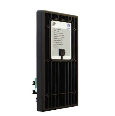
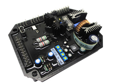
DECS-150
The BASLER regulator DECS-150, Digital Excitation Control Systems, is suitable for increasing the X-TYPE series alternator adjustment and protection functions.
It offers accurate control of the excitation of the machine in a compact product. The adaptability to many applications of the DECS-150 is guaranteed by configurable inputs and outputs, flexible communication capabilities and programmable logic implemented with the supplied software. The high flexibility and powerful features make this device particularly useful in those projects where the machines are connected in parallel with other generators and/or the utility system, since the grid code requirements are very demanding. It is ideal for distributed generation, cogeneration plants and in peak shaving applications.
Specifically, it allows additional functions such as "Dead Bus Paralleling", droop control and cross current compensation between parallel generators. It can provide alarms and/or alerts for diode failures, overvoltage, undervoltage, overfrequency, underfrequency.
The DECS-150 can be powered either by PMG, MAUX (auxiliary winding) or even by SHUNT excitation. The X-TYPE series alternators, also known as the Mecc Alte medium and high voltage series, are designed with PMG excitation.
It is supplied on customer request according to the project requirements. This type of regulator is installed inside the alternator auxiliary box. The AVR is pre-set according to customer requirements.
Excitation power is provided by the DECS-150 through a filtered switching power module that uses the pulse width modulation method (PWM). It is able to supply 7Adc with an ambient temperature of 70 ° C and has a forcing capacity of 11Adc for 10 seconds.
If it is necessary to install a redundant hot swap excitation system, upon request, we offer the Dual DECS-150 model. This is an integrated system that increases the reliability of the alternator. In this configuration the Dual DECS-150 is supplied on a mounting plate that must be housed in the customer's control panel.
Characteristics
| DC Operating Power | |
| Full Load Continuous Current | 10 A at 55°C 7 A at 70°C |
| AC Operating Power | |
| Power Input Configuration | 1-phase 3-phase |
| Power Input Frequency | dc, 50 to 500 Hz |
| Nominal Input Voltage | 120 ÷ 240 Vac 250 Vdc |
| Generator and Bus Voltage Sensing | |
| Configuration | 1-phase 3-phase–3-wire |
| 50 Hz Voltage Ranges | 100 Vac ±10% 200 Vac ±10% 400 Vac ±10% |
| 60 Hz Voltage Ranges | 120 Vac ±10% 240 Vac ±10% 480 Vac ±10% 600 Vac ±10% |
| Frequency | 50/60 Hz nominal |
| Burden | |
| Generator Current Sensing | |
| Configuration | 1-phase or 3-phase with separate input for cross-current compensation |
| Nominal Current | 1 Aac |
| Frequency | 50/60 Hz |
| Burden | <0,1 VA |
| Environmental | |
| Operating Temperature (10 A Continuous) | –40°C to 55°C |
| Operating Temperature (7 A Continuous) | –40°C to 70°C |
| Storage Temperature | –40°C to 85°C |
| Communication | |
| USB | USB type B port |
| Ethernet | RJ45 jack 10BASE-T 100BASE-TX |
Features
| Voltage regulation accuracy ±0,25% |
| THD-tolerant design offers reliable operation with nonlinear loads |
| True RMS three-phase generator voltage sensing/regulation |
Four excitation control modes:
|
| Auto tuning feature |
| Soft start and voltage buildup control |
| Integrated droop and cross current compensation |
| Diodes failure detection |
| Remote setpoint control input accepts analog voltage or current control signal |
| Real-time metering |
Wide range of limiting and protection functions:
|
| Eight programmable contact-sensing inputs |
| Three contact outputs |
| Flexible communication: Serial communication through USB port and Ethernet communication |
| Data logging and sequence of events |
| USB powered for programming via BESTCOMSPlus software |
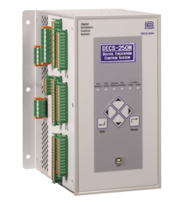
DECS-250
Additional features are implemented on the DECS-250 controller, Digital Excitation Control System. It is a high-level excitation system that covers 100% of applications up to 10 MW for power plants. This system is generally required for Oil & Gas applications and/or in energy production markets, where the specifications are very demanding.
It is supplied on customer request according to the project requirements. The DECS-250 can be powered either by SHUNT, PMG3, MAUX (auxiliary winding) or DC. The X-TYPE series alternators are excited through the aid of a permanent magnet synchronous generator (PMG).
This type of regulator cannot be installed on the machine due to its size. It must be housed and wired inside the genset control panel. The AVR is pre-set according to customer requirements.
Excitation power is provided by the DECS-250 via a filtered switching power module using the pulse width modulation method (PWM). It is able to supply 15A with an ambient temperature of 70 ° C and has a forcing capacity of 30A for 10 seconds.
If it is necessary to install a redundant hot swap excitation system, upon request, we offer the Dual DECS-250 model. This is an integrated system that increases the reliability of the alternator. In this configuration the Dual DECS-250 is supplied on a mounting plate that must be housed in the customer's control panel.
Characteristics
| DC Operating Power | |
| Full Load Continuous Current | 20 A at 55°C 15 A at 70°C |
| AC Operating Power | |
| Power Input Configuration | 1-phase 3-phase |
| Power Input Frequency | 50 to 500 Hz |
| Nominal Input Voltage | 60 ÷ 240 Vac |
| Generator and Bus Voltage Sensing | |
| Configuration | 1-phase 3-phase–3-wire |
| 50 Hz Voltage Ranges | 100 Vac ±10% 200 Vac ±10% 400 Vac ±10% |
| 60 Hz Voltage Ranges | 120 Vac ±10% 240 Vac ±10% 480 Vac ±10% 600 Vac ±10% |
| Frequency | 50/60 Hznominal |
| Burden | < 1 VA per phase |
| Generator Current Sensing | |
| Configuration | 1-phase or 3-phase with separate input for cross-current compensation |
| Nominal Current | 1 Aac or 5Adc |
| Frequency | 50/60 Hz |
| Burden with 1 Aac Sensing | <5 VA |
| Burden with 5 Aac Sensing | <10 VA |
| Environmental | |
| Operating Temperature (20 Adc Continuous) | –40°C to 55°C |
| Operating Temperature (15 Adc Continuous) | –40°C to 70°C |
| Storage Temperature | –40°C to 85°C |
| Communication | |
| USB | USB type B |
| Ethernet | 10BASE-T (standard) 100BASE-TX (optional) |
| RS-232 | RS-232, 9 pin, sub D for optional external autotracking |
| RS-485 | Modbus RTU protocol |
| CAN BUS | One port for ECU communications and one port for expansions modules |
Features
| High performance automatic voltage regulation accuracy (±0,25%) |
| THD-tolerant design offers reliable operation with nonlinear loads |
| RMS value three-phase generator voltage and current sensing/regulation |
Four excitation control modes:
|
| Auto tuningfeature with two PID stability groups |
| Integrated Generator Protection (27/59, 81O/U, 32R, 40Q), EDM, 59F,51F, Loss of PMG, Field Short Circuit, and 25 Sync Check |
| Integrated droop control and cross current compensation |
| Reactive Power sharing over Ethernet |
| Optional Integrated power system stabilizier (PSS) |
| Real-time metering |
Wide range of limiting and protection functions:
|
| Sixteen Programmable Contact Inputs |
| Eleven Programmable Contact Outputs plus one watchdog |
| Data logging and sequence of events |
Programming using the BESTCOMS Plus software. Simplification of the AVR setup with programmable drag-and-drop logic. |
| Grid code settings provide compatibility with grid code compliant systems. |
In the X-TYPE series alternators, temperature readings are provided, using PT100 RTD, in the stator windings and on the bearings. Furthermore, the mechanical predisposition of the vibration sensors is foreseen, on the larger machines of the series of medium and high voltage alternators, on NDE and DE side.
STATOR WINDING PT100
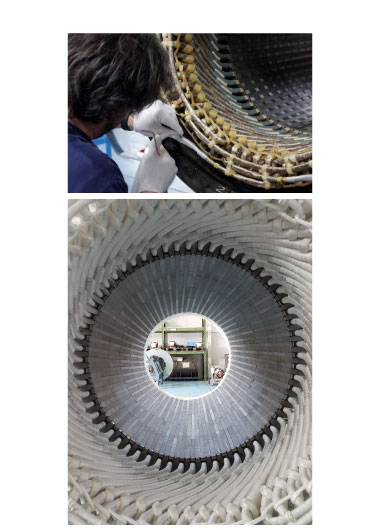
The temperature detection of the stator windings in medium and high voltage alternators is carried out using 3-wire PT100 temperature sensors. As standard, Mecc Alte uses No.6 PT100.
The sensors are mounted inside the stator slots, to measure the temperature of the windings for all three phases. The sensors are installed in such a way to guarantee redundancy and therefore greater reliability for the customer.
Temperature sensing provides important information regarding the behaviour of the generator, allowing to prevent dangerous situations and extraordinary service interruptions for the generator and the plant. If the thermal class of the machine is exceeded, an alarm signal will be activated.
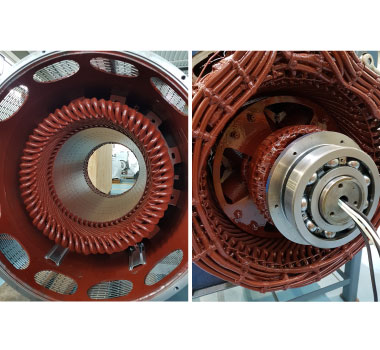
BEARING PT100
The bearing PT100s are installed in the main bearing ring, near the outer raceway.
Each bearing of X-TYPE series alternators can be equipped with PT100 on request. If needed, each bearing can be equipped with dual PT100, to ensure signal redundancy and therefore greater reliability.
In the engineering phase it is also possible to provide temperature sensors for the stator lamellar pack and for the air entering and leaving the machine
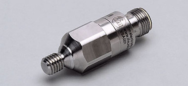
VIBRATION SENSING
Single-axis accelerometers are used to detect vibrations in alternators. They can be installed on the bearings, on brackets or on couplings on the main 3 x-y-z axes.
By acquiring the signal coming from the vibration sensors, suitably conditioned, it is possible to analyse the behaviour of the generator and qualitatively evaluate its state, in some cases highlighting anomalies such as:
- Possible imbalances;
- Possible dissymmetries and misalignments;
- Possible incompliances of certain components.
The ECO49 X-TYPE models are equipped as standard with the provision, in the brackets, for the installation of radial vibration sensors (x-axis, one for each bracket). The sensors and the relative wiring are supplied on request.
In the ECO43, ECO46 and ECO47 X-TYPE models, the mechanical arrangement of the sensor housing is available upon request during the engineering phase.
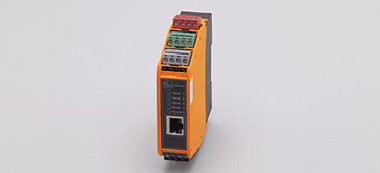
The sensors are designed to be connected to an external control unit that conditions the signal to make it available to the main monitoring systems. It can be housed inside the auxiliary terminal box upon evaluation in the engineering phase. It can be alternatively installed and wired in cabinets outside the generator.
Accelerometers, together with signal reading units, are available upon request.
The standard configuration is represented by a sensor, mounted on the brackets, on the coupling side on the X axis + another sensor installed on the opposite side on the X axis.
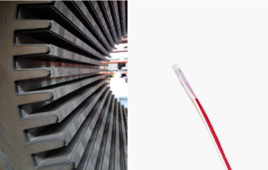
INSULATION SYSTEM
Mecc Alte Power Products has developed in collaboration with Von Roll, since 2017, an insulation system that represents the state of the art of class H systems. It combines mica tapes and epoxy resin with low viscosity. This technology allows to obtain excellent thermal and longevity performances. The whole Mecc Alte X-TYPE range of medium and high voltage generators is based on this insulation technology.
Main advantages:
- Excellent resistance to thermo-mechanical aging (thermal index 192°C - IEC 60216);
- Mechanical properties suitable for MV / HV windings;
- Good thermal conductivity and good electrical properties;
- Approved by the American Petroleum Institute (API) for application in harsh environments;
The insulation system has passed the Functional-System Test required by IEC 60034-18-31 / IEEE 1776 which includes thermal tests, vibrations, humidity and dielectric strength. Certificates are available upon request.
Each stator of the X-TYPE series of medium and high voltage is tested at all production stages, for example before and after the VPI (Vacuum Pressure Impregnation) cycle; in this way we guarantee the highest quality and reliability of the sold product.
The dedication that Mecc Alte has placed, in recent years, in the development of the insulation system has led to excellent results. The reliability and resistance that have been achieved have allowed us to extend the warranty to 4 years for all the medium and high voltage parts of the X-TYPE series alternators

![]()
EPOXY COATING FOR MARINE OR HIGHLY AGGRESSIVE ENVIRONMENTS
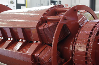
A layer of protective enamel for high temperatures is applied to the impregnated and polymerized windings to ensure greater resistance to aggressive environments (humidity and chemical agents). It also provides mechanical protection due to abrasion resistance.
The epoxy coating (red enamel) is a standard treatment for the stator windings on the entire X-TYPE series of MV&HV. This protection is applied both on the main stator and on the exciter stator. As for the main rotor and exciter rotor, the coating is applied as standard only for the ECO47 and ECO49 series.
This type of protection allows Mecc Alte to guarantee a product of higher quality and reliability on the market.
In the smaller machines of the ECO series (ECO43 and ECO46), the epoxy coating for the main rotor and for the exciter is applied upon request.
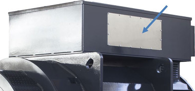
AMAGNETIC SIDE PANELS
The X-TYPE series of medium and high voltage alternators are supplied as standard with a perforated amagnetic panel for the cable outlet.
The panels are made of stainless steel AISI 304 which avoids the arising of Eddy currents and consequently eliminates the hotspots near the cable glands.
ANTICONDENSATION HEATERS
Anti-condensation heaters are standard accessories for the entire X-TYPE Series Mecc Alte.
In models ECO43, ECO46 and ECO47 they are installed inside the alternator stator casing. These are 300W components (600W on ECO47) with standard single-phase power supply. In the ECO49 family models, the heaters are housed in dedicated compartments inside the stator casing. The power is increased to 600W.
Their arrangement allows easy replacement in case of failure.
Potentially, all rotating electrical machines can have some problems related to shaft voltages, regardless of the nominal electrical parameters of the machine.
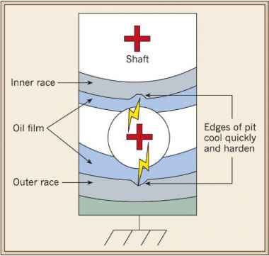
Shaft voltages are not harmful by themselves. The problem arises when there is a closed path that allows the circulation of currents through the alternator bearings. These currents can cause erosion, which leads to fast bearing wear. When these particular voltages reach a level sufficient to overcome the dielectric properties of the grease present inside the bearing (usually, around 15 - 20 V), electric discharge phenomena occur. These generated electric currents flow through the path of less resistance - typically through the generator bearings – closing themselves on the alternator housing (ground). These discharges cause grooves on the bearing tracks. This phenomenon of erosion becomes more and more intense until the bearing is completely worn, causing forced stops for maintenance.
This phenomenon is linked to several causes, including:
- Rotor magnetic dissymmetries;
- Shaft residual magnetism;
- Electrostatic fields from external and internal sources (for example, in applications with hydraulic and steam turbines);
- High frequency disturbance sources (MHz) - Inverter - Power supplies;
- High frequency disturbances from the network, for example "direct grid connected" applications.
The aforementioned causes can produce the e.m.f. on the shaft, more or less intense according to the occurring causes. The design and production processes, as well as the accuracy in the realization of the most critical elements, can influence this phenomenon.
In general, the values of the e.m.f. induced are rather small (in the order of 100-300 mV), such as to not generate circulation currents on the shaft.
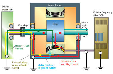
For example, in backup generator sets application, the greatest danger is the presence of Variable Frequency/Speed Drives (VFD) which can induce high frequency common mode voltages.
Capacitive couplings inside the alternator, having low impedance at high frequencies, can cause very high circulating currents. In these applications, it may happen that the e.m.f on the shaft generates currents that are closed through the bearings, producing erosion and wear of the same.
This is a vicious circle because erosions, grooves and dissymetries in the bearing tracks increase the local intensity of the electric field, thus increasing the damage caused by the phenomenon.
To mitigate the effects of shaft currents, two methods are normally used: the insulation of the bearing and the shaft grounding. These two ways can be used together or separately.
INSULATED BEARING - CERAMIC COATING
Both the front and rear bearings of the X-TYPE ECO43, ECO46 and ECO47 models are available, optionally upon customer's request, with an insulating ceramic coating.
The coating is usually composed of aluminium oxide powder, sprayed with a plasma jet on the outer or inner ring. In this way, the oxide layer adheres optimally to the base material. The insulating layer offers an insulation resistance greater than 200 MΩ and can be tested at least 500 VDC.
Insulated bearings are interchangeable with standard ones.
INSULATED BEARING - FIBERGLASS RING
For the X-TYPE ECO49 series, the bearing housing is available on request with a special arrangement.
Unlike the other models, where the bearings are insulated, the bearing box is made completely insulated by fiberglass rings. This solution is durable and offers very high insulation between the bearing and the alternator housing. Resistance greater than 1 GΩ. In the order phase and upon request, it is possible to request the isolation of both the DE and NDE bearings.
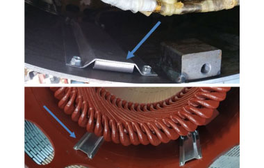
SHAFT GROUNDING RING OR BRUSH
As an alternative or in combination with the insulation of the bearings it is advisable to create low-impedance paths for these currents. In this regard, it is possible to install rings / brushes in graphite or with conductive microfibres, capable of draining the shaft current. Mecc Alte uses AEGIS ® rings from Electro Static Technology, a leading company in bearing protection systems. This ring can be installed on the DE or NDE shaft end on the bearing support.
Compared to the collector / brush solution, the microfibre rings do not require maintenance and their ability to pick up high-frequency currents has been fully demonstrated.
Generally, for the gensets, the shaft grounding is accomplished at the drive end side, in combination with an insulated bearing at the opposite drive end.
Shaft grounding ring is optionally available for the entire medium and high voltage X-TYPE series of Mecc Alte alternators.
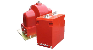
The Mecc Alte X-TYPE series Medium and High Voltage generator (up to 13.8 kV) include one or more current and voltage transformers inside the terminal box. These are accessories of fundamental importance in the MV / HV alternators, for the following reasons:
- To transform the voltage and current values with values that can be easily managed by the data acquisition systems (measurement and / or protection) installed on site, otherwise not directly measurable.
- To galvanically decouple the primary circuit (HV/MV) and the measurement circuit (LV).
- They are installed inside the generator, ensuring a more compact solution than mounting them in an external switchboard.
Several configurations are available based on the specific project requirements of the customer. The best solutions are studied, both in terms of performance and in layout inside the terminal box. For a correct operation, the measuring transformers must be chosen and sized in compliance with the nominal machine sizes within the limits dictated by the technical standards.
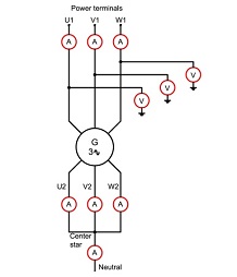
Mecc Alte offers, as standard, a minimum configuration, suitable to guarantee the operating characteristics required by the customer. This configuration involves the installation of two transformers on board of the machine, one of voltage and one of current:
- No.1 VT Ph-Ph, Un / 100V 15VA cl.05
Phase to Phase voltage transformer, indispensable for voltage regulation (dedicated, therefore, to provide sensing to the voltage regulator – Mecc Alte DER2A or Basler DECS models). - N. 1 CT, In / 1 A 15VA cl.05 FS10
Current measurement transformer, dedicated to supply the current sensing to the external measurement / acquisition system (genset control unit) or to the AVR Basler DECS (function not available with AVR DER2A). Current sensing is used to set functions such as power factor control (PF) and / or reactive power, setting the over-excitation and excitation limits, droop control setting and much more.
The use of this type of products allows to adequately manage the main parameters of a synchronous generator, guaranteeing the correct operation of the alternator and / or protection from anomalous operations.
Inside the standard terminal boxes, for all the models of the X-TYPE series, it is possible to accommodate up to a maximum of three VTs and three CTs. Customers, based on their project needs, can request transformers with specific technical features such as:
- Number of transformers: the measurement of all the phase currents or only one of them, as well as the measurement of the single phase-to-phase voltage or of all three phase voltages.
- Transformation ratio: for example, with nominal secondary currents 1-5 A or dedicated.
- Number of secondary windings: if both a protection and a measurement circuit are required, and compatibly with the other required characteristics, a transformer with double secondary winding will be supplied (constructively, the measurement windings and protections have technical specificities).
- Accuracy class: for example, as regards of the secondary measurement circuit of a CT, the normalized values are 0.1 / 0.2 / 0.2s / 0.5 / 0.5s / 1/3/5;
- Other customizations are available, such as:
- secondary VT voltages such as 100-110-120 VAC;
- regulatory standards such as IEC, DIN, VDE, ANSI, BS;
- accuracy classes (including class X) and performance classes;
- CTs to be used for differential protection can be requested;
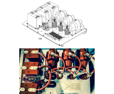
Example of layout with 3 CT and 3 VT configuration
The most requested configurations are:
- Phase-phase voltage transformer and three current transformers:
No.1 VT phase-phase, Un / 100V 15VA cl.05
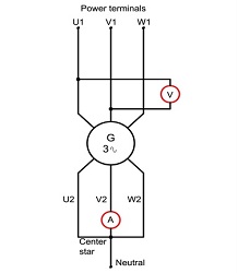
No.3 CTs for measurement and protection In / 1A 15VA cl.05 FS10 / 1A 15VA 5P10; - Three single-phase voltage transformers and three current transformers:
No.3 single-phase VTs, Un: √3 / 100: √3 V 15VA cl.05
No.3 CTs for measurement and protection In / 1A 15VA cl.05 FS10 / 1A 15VA 5P10; - If required by the project specifications, and if compatible with the technical feasibility, it is possible to foresee the installation of a neutral CT in the terminal box. With this configuration, therefore, there are a total of four CTs and three VTs installed on the machine.
It should be noted that the X-TYPE series ECO47 and ECO49 alternators have a larger standard terminal box than the ECO43 and ECO46 models; in fact, it is possible to accommodate up to seven CTs and three VTs. This configuration lends itself to the implementation of an on-board machine differential protection (87G).
ADDITIONAL TERMINAL BOX
For sectors such as Oil & Gas and Power Generation, the specifications for VTs and CTs are more demanding. Often, it is required a greater number of measurement / protection transformers than other applications, as well as better performance.
In the event that there is not enough space in the standard terminal boxes or it is explicitly required for the project, it is necessary to foresee the separation into two distinct units; one box for the main line and one box for the star center. This option is available only for the ECO47 and ECO49 series.
Normally, these accessories are installed and wired directly by Mecc Alte when assembling the alternator. It is therefore necessary to define the number of transformers and their configuration at the time of the order or during the first phase of engineering.
We recommend always asking Mecc Alte Application Engineers for special configurations. We evaluate them with our suppliers to choose the most correct solution.
ROTOR EARTH FAULT DETECTION (ANSI 64R)
The 64R protection called "rotor ground" consists of a continuous monitoring of the insulation of the rotor windings. During normal operation of the generator, rotor windings are subjected to electrodynamic and centrifugal forces as well as possible voltage spikes. Therefore, it is important to guarantee the maximum reliability and robustness of the system through the design of the components and the management of the production processes.
The excitation winding, wrapped on the rotor poles, is isolated from the ground under normal conditions. This insulation is guaranteed by:
- Insulation of the from-wound (inter-turn);
- Winding isolation from the rotor magnetic core.
Following an anomalous event, If an electrical contact occures between the winding and ground, a so-called "hot spot" can be generated, i.e. a point where there is overheating; however, there is no active current circulation, since the electrical circuit is not closed. If, instead, a second contact point is generated, the excitation current circulating in the winding will be directed to a different path than the designed one, producing a short circuit between turns with consequences in terms of magnetic vibrations and unbalances.
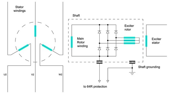
The monitoring is performed by applying a common mode voltage (alternating or continuous) between the rotor winding and the shaft.
The current can only close due to a loss of insulation, or through parasitic capacitances. The value of the insulation impedance is derived from the current analysis. Normally, it is possible to discriminate also the number of points of contact between winding and mass.
The resulting injected current signal is then connected to an analog input, able to discern the capacitive component from the resistive one. When the rotor is completely isolated, the impedance is purely capacitive.
When one point goes to ground, the relay detects a resistive type component and generates a signal that can be managed to activate an alarm or a stop command.
For the two largest families of the X-TYPE series (ECO47 and ECO49), as an option and at customer's request, provision is made for 64R protection, through the installation of a dedicated brush on the rectifier bridge, where the voltage injection takes place by the external control unit. Usually, the shaft grounding is also planned.
To learn more about how our alternator accessories can streamline your processes and make life easier across the powergen industry, please don’t hesitate to get in touch and find the best solutions for you.